 8051 Development Board
 Advance Development Boards
 Arduino boards
 ARM Microcontroller
 AVR Microcontroller Board
 Pic Devlopment Board & programmer
 Led lights & Strips
 PCBs & Breadboard
 Potentiometer
 Power Transistors
 Resistor & Smd & inductor
 Switches
 Aluminium Heat Sink
 Buzzer & Speaker
 capacitor
 Crystal Oscillators
 Doides
 Electric Fuses
 ICs & Dips
 Power supply module
 Transformer
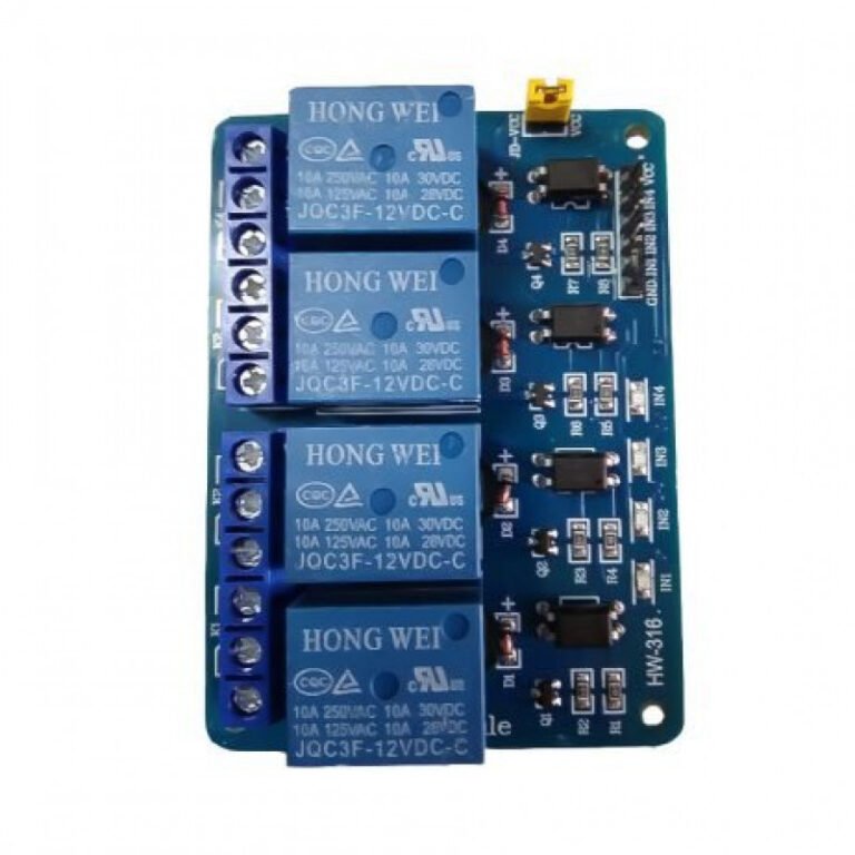
 Relay Module
 Kits
Kits Magnet
 RF Connectors
 PCT and DC Connectors
 Wires & Heat Shrink
 FFC, FPC, Berg connectors
 Nextion
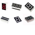 Segment
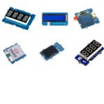 Seedstudio
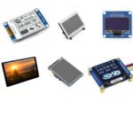 Waveshare
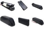 E Bike Batteries
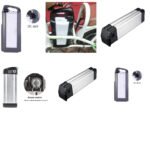 E bike Battery Case
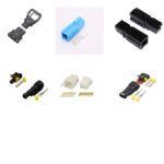 E bike Connectors
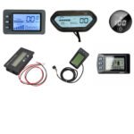 E bike Display
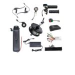 E bike Kit
 E bike Motors & Controllers
 Electronics Accessories
 Mechanical Accessories
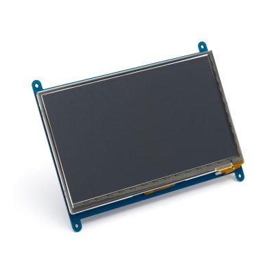
 Display
 Cameras


-
 Pick up from the Robotwala Store
-
Shiprocket from Air
-
Shiprocket from Surface
 Pick up from the Robotwala Store
 Shiprocket from Air
 Warranty 1 year
 Free 30-Day returns
In stock
In stock
In stock
In stock

 Audio Amplifier Module
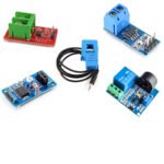 Current & Volatage Sensor
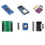 Breakout Board
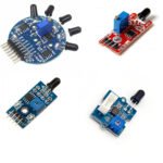 Flame Sensors
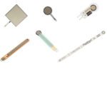 Force Sensor
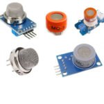 Gas Sensors
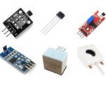 Hall Effect Sensor
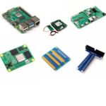 Boards & Modules
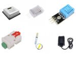 Humidity & Temperature Sensor
 LED Module
 PIR Sensor
 Pressure Sensors
 Proximity Sensor
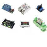 Relay Module
 Real Time Clock (RTC) Module
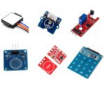 Touch Sensor
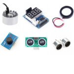 Ultrasonic Sensor
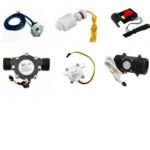 Water Level & Water Flow Sensor
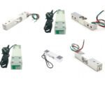 Weighing Scale Sensor


 LED ModulePIR SensorPressure SensorsProximity SensorReal Time Clock (RTC) ModuleTouch SensorUltrasonic SensorWater Level & Water Flow SensorWeighing Scale Sensor
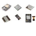 Ai Thinker ESp Wifi ModuleAudio Amplifier ModuleHumidity & Temperature SensorHall Effect SensorGas SensorsFlame SensorsBreakout BoardCurrent & Volatage SensorForce Sensor


No account yet?
Create an Account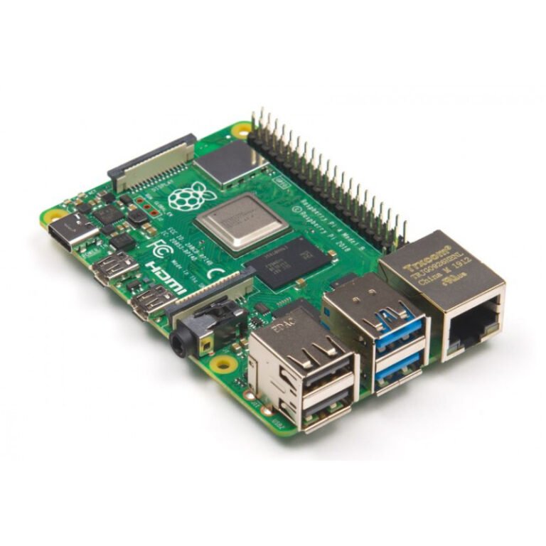
Reviews
Clear filtersThere are no reviews yet.