


 Sensors & Module
 LED Module
 PIR Sensor
 Pressure Sensors
 Proximity Sensor
 Real Time Clock (RTC) Module
 Touch Sensor
 Ultrasonic Sensor
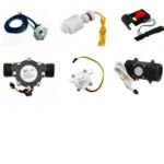 Water Level & Water Flow Sensor
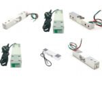 Weighing Scale Sensor
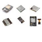 Ai Thinker ESp Wifi Module
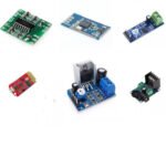 Audio Amplifier Module
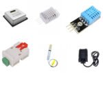 Humidity & Temperature Sensor
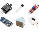 Hall Effect Sensor
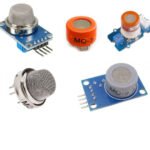 Gas Sensors
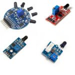 Flame Sensors
 Breakout Board
 Current & Volatage Sensor
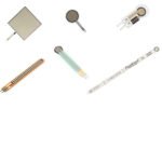 Force Sensor
 Boards & Programmer


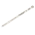
The FlexiForce A201 force sensor is an ultra-thin and flexible printed circuit, which can be easily integrated into most applications.
Hurry and get discounts on all Apple devices up to 20%
Sale_coupon_15
₹2,999.00 Original price was: ₹2,999.00.₹2,959.00Current price is: ₹2,959.00.
Inclusive of GST
To pick up today
Free
Our courier will deliver to the specified address
3-4 Days
139
courier will deliver to the specified address
5-7 Days
90
Payment Methods:
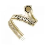
The FlexiForce A201/1 flex sensor is an ultra-thin and flexible printed circuit, which can be easily integrated into most applications. With its paper-thin construction, flexibility and force measurement ability, the FlexiForce force sensor can measure force between almost any two surfaces and is durable enough to stand up to most environments. FlexiForce has better force sensing properties, linearity, hysteresis, drift, and temperature sensitivity than any other thin-film force sensors.
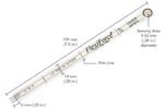
The “active sensing area” is a 0.375” diameter circle at the end of the sensor. The sensor has two layers of the substrate. This substrate is composed of polyester film (or Polyimide in the case of the High-Temperature Sensors). On each layer, a conductive material (silver) is applied, followed by a layer of pressure-sensitive ink. The adhesive is then used to laminate the two layers of substrate together to form the sensor. The silver circle on top of the pressure-sensitive ink defines the “active sensing area.”
Silver extends from the sensing area to the connectors at the other end of the sensor, forming the conductive leads.
FlexiForce sensors are terminated with a solderable male square pin connector, which allows them to be incorporated into a circuit. The two outer pins of the connector are active and the centre pin is inactive. The length of the sensors can be trimmed to predefined lengths of 2”, 4” and 6” as per the requirements. If the sensor is trimmed, a new connector must be attached. This can be accomplished by purchasing staked pin connectors and a crimping tool. A conductive epoxy can also be used to adhere to small wires to each conductor.
The sensor acts as a variable resistor in an electrical circuit. When the sensor is unloaded, its resistance is very high (greater than 5 Meg-ohm); when a force is applied to the sensor, the resistance decreases. Connecting an ohmmeter to the outer two pins of the sensor connector and applying a force to the sensing area can read the change in resistance.
An example circuit is shown below. In this case, it is driven by a -5 V DC excitation voltage. This circuit uses an inverting operational amplifier arrangement to produce an analog output based on the sensor resistance and a fixed reference resistance (RF). An analog-to-digital converter can be used to change this voltage to a digital output. In this circuit, the sensitivity of the sensor could be adjusted by changing the reference resistance (RF) and/or drive voltage (VT); a lower reference resistance and/or drive voltage will make the sensor less sensitive and increase
its active force range.
The sensing area is the silver circle on the top of the sensor only.
Typical Performance:
Specifications:
| Connector | 3-pin male square pin (center pin is inactive) |
| Drift | < 5% per logarithmic time scale |
| Force Range | 0-4.4N (0-0.45kg) |
| Hysteresis | < 4.5 % of full scale |
| Length ( cm ) | 8 Inch (20.3 cm) |
| Linearity (Error) | < ±3% of full scale |
| Max Current (A) | 0.2 |
| Operating Temperature Range (°C) | -9 to 60 |
| Operating Voltage (VDC) | 5 |
| Pin Spacing (mm) | 2.54 |
| Repeatability | +/-2.5% of Full Load |
| Response Time ( μS) | 5 |
| RoHS Compliant | Yes |
| Sensing Area (mm) | 9.53 |
| Surface Layer | Polyester |
| Thickness (mm) | 0.203 |
| Width (mm) | 14 |
| Shipment Weight | 0.006 kg |
| Shipment Dimensions | 6 × 1 × 1 cm |
1 x FlexiForce A201/1 Flex Sensor
Operating voltage | 2.5 3.0V |
Pixel Resolution | 0.3MP |
Photosensitive array | 640 x 480 |
Optical Size | 1.6 inch |
Angel of view | 67 degrees |
Maximum Frame Rate | 30fps VGA |
Sensitivity | 1.3V/(Lux-sec) |
Dormancy | Less than 20A |
Power consumption | 60mW/15fpsVGA YUV |
Temperature operation Range | -30 C ~ 70 C |
Pixel area | 3.6 x 3.6 m |
Signal to noise ratio (SNR) | 46 dB |
Dynamic range | 52 dB |
In stock
In stock
In stock
In stock
In stock






No account yet?
Create an Account
Reviews
Clear filtersThere are no reviews yet.