


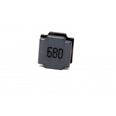
68uH 890mA SMD Coupled Inductor
This is a 68uH 20% 0.507 Ohm 890 mA Coupled Inductor. It is a Coupled Inductor with a low DCR and high rated current surface mount SMD power inductor. These are lead-free products, RoHS compliant. These inductors are widely used in buck converter, laptop, displays, network communication equipment, and etc.
74HC123 IC – (SMD Package) – Dual Retriggerable Monostable Multivibrator IC (74123)

74HC137 IC – (SMD Package) – 3-to-8 line Decoder/Demultiplexer IC (74138 IC)

74HC158 IC – (SMD Package) – Quad 2-Input Multiplexer IC (74158 IC)

74HC161 IC – (SMD Package) – 4-Bit Presettable Synchronous Binary Counter IC (74161)
The 74HC161 is a synchronous presettable binary counter with an internal look-head carry. Synchronous operation is provided by having all flip-flops clocked simultaneously on the positivegoing edge of the clock (CP). The outputs (Q0 to Q3) of the counters may be preset HIGH or LOW. A LOW at the parallel enable input (PE) disables the counting action and causes the data at the data inputs (D0 to D3) to be loaded into the counter on the positive-going edge of the clock. Preset takes place regardless of the levels at count enable inputs (CEP and CET). A LOW at the master reset input (MR) sets Q0 to Q3 LOW regardless of the levels at input pins CP, PE, CET and CEP (thus providing an asynchronous clear function). The look-ahead carry simplifies serial cascading of the counters. Both CEP and CET must be HIGH to count. The CET input is fed forward to enable the terminal count output (TC). The TC output thus enabled will produce a HIGH output pulse of a duration approximately equal to a HIGH output of Q0. This pulse can be used to enable the next cascaded stage. The maximum clock frequency for the cascaded counters is determined by the CP

74HC163 IC – (SMD Package) – Presettable synchronous Binary counter IC (74163)
The 74HC163; 74HCT163 is a synchronous presettable binary counter with an internal look-head carry. Synchronous operation is provided by having all flip-flops clocked simultaneously on the positive-going edge of the clock (CP). The outputs (Q0 to Q3) of the counters may be preset to a HIGH or LOW. A LOW at the parallel enable input (PE) disables the counting action. It causes the data at the data inputs (D0 to D3) to be loaded into the counter on the positive-going edge of the clock. Preset takes place regardless of the levels at count enable inputs (CEP and CET). A LOW at the master reset input (MR) sets Q0 to Q3 LOW after the next positive-going transition

 Boards & Modules
 ARM Microcontroller
 AVR Microcontroller Board
 Arduino boards
 Advance Development Boards
 8051 Development Board
 Audio Amplifier Module
 Current & Volatage Sensor
 Breakout Board
 Flame Sensors
 Force Sensor
 Gas Sensors
 Hall Effect Sensor
 Humidity & Temperature Sensor
 LED Module
 PIR Sensor
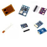 Pressure Sensors
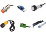 Proximity Sensor
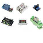 Relay Module
 Real Time Clock (RTC) Module
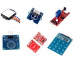 Touch Sensor
 Ultrasonic Sensor
 Water Level & Water Flow Sensor
 Weighing Scale Sensor


 Ai Thinker ESp Wifi Module
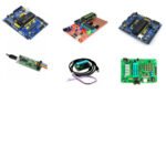 Pic Devlopment Board & programmer
 Led lights & Strips
 PCBs & Breadboard
 Potentiometer
 Power Transistors
 Resistor & Smd & inductor
 Switches
 Aluminium Heat Sink
 Buzzer & Speaker
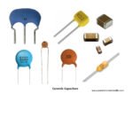 capacitor
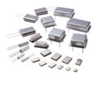 Crystal Oscillators
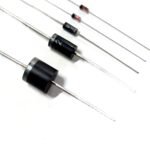 Doides
 Electric Fuses
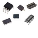 ICs & Dips
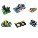 Power supply module
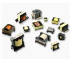 Transformer
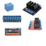 Relay Module
 Kits
Kits Magnet
 RF Connectors
 PCT and DC Connectors
 Wires & Heat Shrink
 FFC, FPC, Berg connectors
 Nextion
 Segment
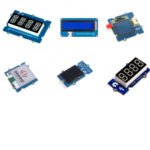 Seedstudio
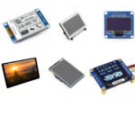 Waveshare
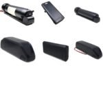 E Bike Batteries
 E bike Battery Case
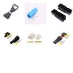 E bike Connectors
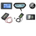 E bike Display
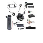 E bike Kit
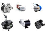 E bike Motors & Controllers
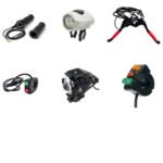 Electronics Accessories
 Mechanical Accessories
 Display
 Cameras