


74595 IC (SMD Package)- 8-bit serial-in/serial or parallel-out shift register IC
The 74595 consists of an 8?bit shift register and an 8?bit D?type latch with three?state parallel outputs. The shift register accepts serial data and provides a serial output. The shift register also provides parallel data to the 8?bit latch. The shift register and latch have independent clock inputs. This device also has an asynchronous reset for the shift register. The 74595 directly interfaces with the SPI serial data port on CMOS MPUs and MCUs.
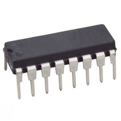
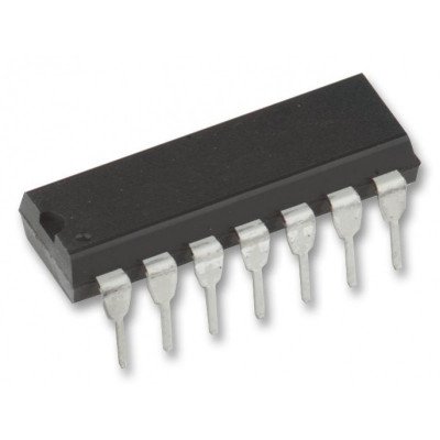
74F109 Positive J-K Positive Edge-Triggered Flip-Flops IC (74109) DIP-16 Package
The 74F109 is a dual positive edge-triggered JK-type flip-flop featuring individual J, K, clock, set, and reset inputs; also true and complementary outputs. Set (SD) and reset (RD) are asynchronous active low inputs and operate independently of the clock (CP) input. The J and K are edge-triggered inputs which control the state changes of the flip-flops as described in the function table. Clock triggering occurs at a voltage level and is not directly related to the transition time of the positive-going pulse. The J and K inputs must be stable just one setup time prior to the low-to-high transition of the clock for predictable operation. The JK design allows operation as a D flip-flop by tying J and K inputs together. Although the clock input is level sensitive, the positive transition of the clock pulse between the 0.8V and 2.0V levels should be equal to or less than the clock to output delay time for reliable operation

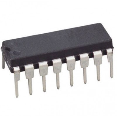
74F113 Dual JK Negative Edge-Triggered Flip-Flop IC (74113) DIP-16 Package
The 74F113 offers individual J, K, Set and Clock inputs. When the clock goes HIGH the inputs are enabled and data may be entered. The logic level of the J and K inputs may be changed when the clock pulse is HIGH and the flip-flop will perform according to the Truth Table as long as minimum setup and hold times are observed. Input data is transferred to the outputs on the falling edge of the clock pulse.
74F138 1-of-8 Decoder/Demultiplexer IC (74138) DIP-16 Package
The 74F138 decoder accepts three binary weighted inputs (A0, A1, A2) and when enabled, provides eight mutually exclusive, active low outputs (Q0 ? Q7). The device features three enable inputs; two active low (E0, E1) and one active high (E2). Every output will be high unless E0 and E1 are low and E2 is high. This multiple enable function allows easy parallel expansion of the device to 1?of?32 (5 lines to 32 lines) decoder with just four 74F138s and one inverter The device can be used as an eight output demultiplexer by using one of the active low enable inputs as the data input and the remaining enable inputs as strobes. Enable inputs not used must be permanently tied to their appropriate active high or active low state.

74F164 8-Bit Serial-in Parallel-Out Shift Register IC (74164) DIP-14 Package
The 74F164 is an 8-bit edge-triggered shift register with serial data entry and an output from each of the eight stages. Data is entered through one of two inputs (Dsa, Dsb); either input can be used as an active High enable for data entry through the other input. Both inputs must be connected together or an unused input must be tied High. Data shifts one place to the right on each Low-to-High transition of the clock (CP) input, and enters into Q0 the logical AND of the two data inputs (Dsa, Dsb) that existed one setup time before the rising edge. A Low level on the Master Reset (MR) input overrides all other inputs and clears the register asynchronously, forcing all outputs Low.

74F182 Carry Lookahead Generator IC (74182) DIP-16 Package

74F194 4-Bit Bidirectional Universal Shift Register IC (74194) DIP-16 Package
The functional characteristics of the 74F194 4-Bit Bidirectional Shift Register are indicated in the Logic Diagram and Function Table. The register is fully synchronous, with all operations taking place in less than 9ns (typical) for 74F, making the device especially useful for implementing very high speed CPUs, or for memory buffer registers. The 74F194 design has special logic features which increase the range of application. The synchronous operation of the device is determined by two Mode Select inputs, S0 and S1. As shown in the Mode Select-Function Table, data can be entered and shifted from left to right (shift right, Q0?Q1, etc.), or right to left (shift left,Q3?Q2, etc.), or parallel data can be entered, loading all 4 bits of the register simultaneously. When both S0 and S1 are Low, existing data is retained in a hold (do nothing) mode. The first and last stages provide D-type Serial Data inputs (DSR, DSL) to allow multistage shift right or shift left data transfers without interfering with parallel load operation. Mode Select and data inputs on the74F194 are edge-triggered, responding only to the Low-to-High transition of the Clock (CP). Therefore, the only timing restriction is that the Mode Select and selected data inputs must be stable one setup time prior to the Low-to-High transition of the clock pulse. Signals on the Mode Select, Parallel Data (D0?D3) and Serial Data(DSR, DSL) can change when the clock is in either state, provide donly the recommended setup and hold times, with respect to the clock rising edge, are observed. The four Parallel Data inputs(D0?D3) are D-type inputs. Data appearing on (D0?D3) inputs whenS0 and S1 are High is transferred to the Q0?Q3 outputs respectively, following the next Low-to-High transition of the clock. When Low, the asynchronous Master Reset (MR) overrides all other input conditions and forces the Q outputs Low

74F240 Octal Buffers/Line Drivers with 3-State Outputs IC (74240) DIP-20 Package
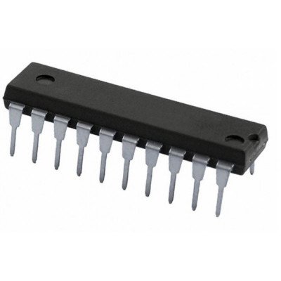
74F244 Octal Buffers/Line Drivers with 3-State Outputs IC (74244) DIP-20 Package
The 74F244 is an octal buffer that is ideal for driving bus lines of buffer memory address registers. The outputs are all capable of sinking 64mA and sourcing up to 15mA, producing very good capacitive drive characteristics. The device features two output enables, OEa and OEb, each controlling four of the 3-State outputs. The 74F244 is functionally equivalent to the 74F244. It has been designed to reduce effects of ground noise. Other advantages are noted in the features

74F251 8-Inputs Multiplexer with 3-State Outputs IC (74251) DIP-16 Package
74F280 9-Bit Parity Generator/Checker IC (74280) DIP-14 Package
The F280 is a high-speed parity generator/checker that accepts nine bits of input data and detects whether an even or an odd number of these inputs is HIGH. If an even number of inputs is HIGH, the Sum Even output is HIGH. I fan odd number is HIGH, the Sum Even output is LOW. The Sum Odd output is the complement of the Sum Even out-put

74F393 Dual 4-Bit Binary Ripple Counter IC (74393) DIP-14 Package
The 74F393 is a Dual Ripple Counter with separate Clock (CPn) and Master Reset (MR) inputs to each counter. The two counters are identified by the ?a? and ?b? suffixes in the pin configuration. The operation of each half of the 74F393 is the same. The counters are triggered by a High-to-Low transition of the Clock (CPa and CPb)inputs. The counter outputs are internally connected to provide Clock inputs to succeeding stages. The outputs of the ripple counter do not change synchronously and should not be used for high speed address decoding. The Master Resets (MRa and MRb) are active High asynchronous inputs; one for each 4-bit counter. A High level in the MR input overrides the Clock and sets the outputs Low
 Boards & Modules
 ARM Microcontroller
 AVR Microcontroller Board
 Arduino boards
 Advance Development Boards
 8051 Development Board
 Audio Amplifier Module
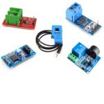 Current & Volatage Sensor
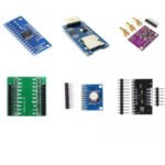 Breakout Board
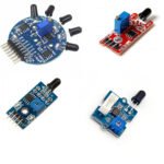 Flame Sensors
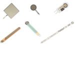 Force Sensor
 Gas Sensors
 Hall Effect Sensor
 Humidity & Temperature Sensor
 LED Module
 PIR Sensor
 Pressure Sensors
 Proximity Sensor
 Relay Module
 Real Time Clock (RTC) Module
 Touch Sensor
 Ultrasonic Sensor
 Water Level & Water Flow Sensor
 Weighing Scale Sensor


 Ai Thinker ESp Wifi Module
 Pic Devlopment Board & programmer
 Led lights & Strips
 PCBs & Breadboard
 Potentiometer
 Power Transistors
 Resistor & Smd & inductor
 Switches
 Aluminium Heat Sink
 Buzzer & Speaker
 capacitor
 Crystal Oscillators
 Doides
 Electric Fuses
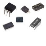 ICs & Dips
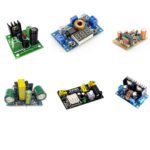 Power supply module
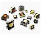 Transformer
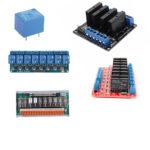 Relay Module
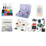 Kits
Kits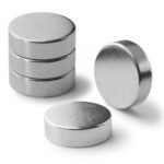 Magnet
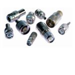 RF Connectors
 PCT and DC Connectors
 Wires & Heat Shrink
 FFC, FPC, Berg connectors
 Nextion
 Segment
 Seedstudio
 Waveshare
 E Bike Batteries
 E bike Battery Case
 E bike Connectors
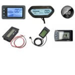 E bike Display
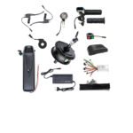 E bike Kit
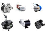 E bike Motors & Controllers
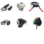 Electronics Accessories
 Mechanical Accessories
 Display
 Cameras