

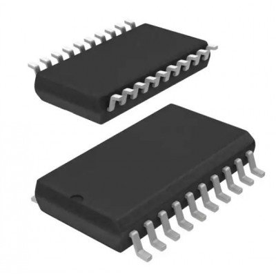
74HC4351 IC – (SMD Package) – 8-Channel Analog Demultiplexer IC (744351)
The 74HC4351; 74HCT4351 is a single-pole octal-throw analog switch (SP8T) suitable for use in analog or digital 8:1 multiplexer/demultiplexer applications. The switch features three digital select inputs (S0 to S2), eight independent inputs/outputs (Yn), a common input/output (Z) and two digital enable inputs (E1 and E2). With E1 LOW and E2 HIGH, one of the eight switches is selected (low impedance ON-state) by S0 to S2. The data at the select inputs may be latched by using the latch enable input (LE). When LE is HIGH the latch is transparent. When E1 is HIGH or E2 is LOW all 8 analog switches are turned off. Inputs include clamp diodes. This enables the use of current limiting resistors to interface inputs to voltages in excess of VCC.

74HC4511 IC – (SMD Package) – BCD to 7 Segment Latch/Decoder/Drivers IC (744511)
The CD54HC4511, CD74HC4511, and CD74HCT4511 are BCD-to-7 segment latch/decoder/drivers with four address inputs (D0-D3), an active-low blanking (BL) input, lamp-test (LT) input, and a latch-enable (LE) input that, when high, enables the latches to store the BCD inputs. When LE is low, the latches are disabled, making the outputs transparent to the BCD inputs. These devices have standard-size output transistors, but are capable of sourcing (at standard VOH levels) up to 7.5 mA at 4.5 V. The HC types can supply up to 10 mA at 6 V.
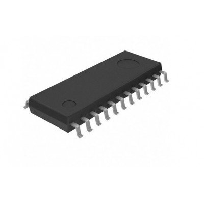
74HC4515 IC – (SMD Package) – 4-to-16 line Decoder/Demultiplexer with Latch IC (744515)
The 74HC4515 is a 4-to-16 line decoder/demultiplexer having four binary weighted address inputs (A0 to A3) with latches, a latch enable input (LE), an enable input (E) and 16 inverting outputs (Q0, to Q15). When LE is HIGH, the selected output is determined by the data on An. When LE goes LOW, the last data present at An are stored in the latches and the outputs remain stable. When E is LOW, the selected output, determined by the contents of the latch, is LOW. When E is HIGH, all outputs are HIGH. The enable input E does not affect the state of the latch. When the device is used as a demultiplexer, E is the data input and A0 to A3 are the address inputs. Inputs include clamp diodes. This enables the use of current limiting resistors to interface inputs to voltages in excess of VCC.
74HC4543 IC – (SMD Package) – BCD to 7 Segment Decoder Driver IC (744543 IC)
The 74HC4543 high-speed silicon-gate device is a BCD to 7-segment latch/decoder/driver designed primarily for directly driving liquid-crystal displays. It has an active-high disable input (LD), an active-high blanking input (BI) and a phase input (PH) to which a square wave is applied for liquid-crystal applications. This square wave also is applied to the backplane of the liquid-crystal display. This device also can be used, in conjunction with current amplifying devices, for driving LEDs, incandescent, fluorescent, and gas-discharge displays. For these applications the phase input provides a means to obtain active-high or active-low segment outputs.

74HC4724 IC – (SMD Package) Dual 8-Bit addressable Latches IC (744724 IC)
These 8-bit addressable latches are designed for general purpose storage applications in digital systems. Specific uses include working registers, serial-holding registers, and active-high decoders or demultiplexers. They are multifunctional devices capable of storing single line data in eight addressable latches, and being a 1-of-8 decoder or demultiplexer with active high outputs

74HC590 IC – (SMD Package) – 8-Bit Binary Counter IC (74590 IC)
The 74HC590 is an 8-bit binary counter with a storage register and 3-state outputs. The storage register has parallel (Q0 to Q7) outputs. The binary counter features master reset counter (MRC) and count enable (CE) inputs. The counter and storage register have separate positive edge triggered clock (CPC and CPR) inputs. If both clocks are connected together, the counter state is always one count ahead of the register. Internal circuitry prevents clocking from the clock enable. A ripple carry output (RCO) is provided for cascading. Cascading is accomplished by connecting RCO of the first stage to CE of the second stage. Cascading for larger count chains can be accomplished by connecting RCO of each stage to the counter clock (CPC) input of the following stage. Inputs include clamp diodes. This enables the use of current limiting resistors to interface inputs to voltages in excess of VCC.


 Boards & Modules
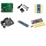 ARM Microcontroller
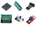 AVR Microcontroller Board
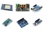 Arduino boards
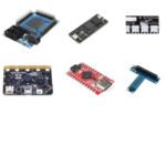 Advance Development Boards
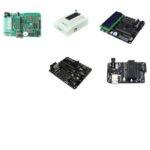 8051 Development Board
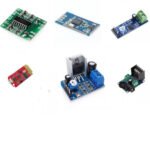 Audio Amplifier Module
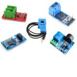 Current & Volatage Sensor
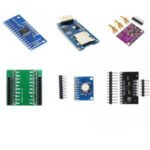 Breakout Board
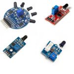 Flame Sensors
 Force Sensor
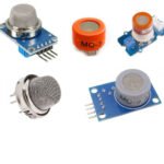 Gas Sensors
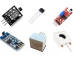 Hall Effect Sensor
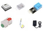 Humidity & Temperature Sensor
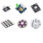 LED Module
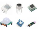 PIR Sensor
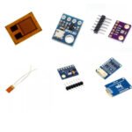 Pressure Sensors
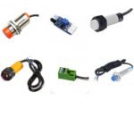 Proximity Sensor
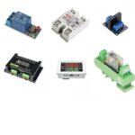 Relay Module
 Real Time Clock (RTC) Module
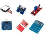 Touch Sensor
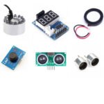 Ultrasonic Sensor
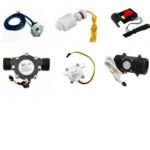 Water Level & Water Flow Sensor
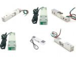 Weighing Scale Sensor


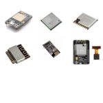 Ai Thinker ESp Wifi Module
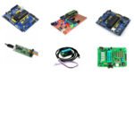 Pic Devlopment Board & programmer
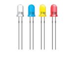 Led lights & Strips
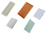 PCBs & Breadboard
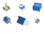 Potentiometer
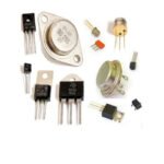 Power Transistors
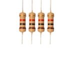 Resistor & Smd & inductor
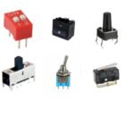 Switches
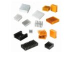 Aluminium Heat Sink
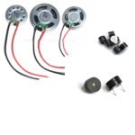 Buzzer & Speaker
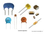 capacitor
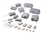 Crystal Oscillators
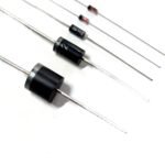 Doides
 Electric Fuses
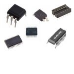 ICs & Dips
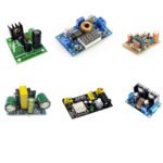 Power supply module
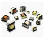 Transformer
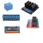 Relay Module
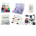 Kits
Kits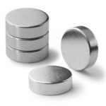 Magnet
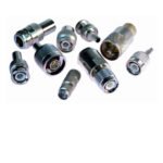 RF Connectors
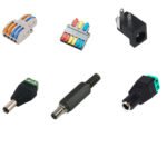 PCT and DC Connectors
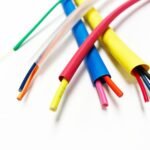 Wires & Heat Shrink
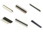 FFC, FPC, Berg connectors
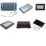 Nextion
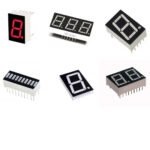 Segment
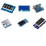 Seedstudio
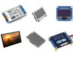 Waveshare
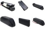 E Bike Batteries
 E bike Battery Case
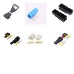 E bike Connectors
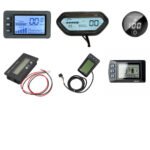 E bike Display
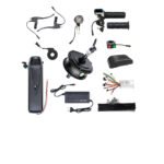 E bike Kit
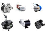 E bike Motors & Controllers
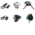 Electronics Accessories
 Mechanical Accessories
 Display
 Cameras